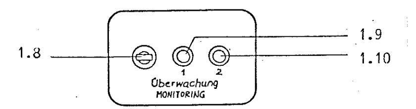
Monitoring (Items 1.8, 1.9, 1.10)
Monitoring lamp 2 indicates blocking of the test channel. If monitoring lamp 2 is not lit, the test channel is operative. Section 1,3 describes the blocking facilities in greater detail.
Monitoring lamp 1 (Item 1.9) serves to indicate inadmissible operating conditions at the transmitter output = primary coil or at the receiver input = secondary coil.
The transmitter voltage must not exceed 10 V since this would otherwise overload the transmitter stage and trouble-free operation would thus no longer be guaranteed. If the transmitter voltage increases above this value, e.g. owing to interruption of the primary coil circuit or incorrect, unsuitable testing transmitters, monitoring lamp 1 lights.
If the monitoring switch (Item 1.8) is switched to upper position, the primary voltage is faded in in the form of a vertical line on the display. Full CRT display = 10 cm line corresponds to 10 V transmitter voltage.
In order to achieve proper functioning with the test coil switch (Item 1.2) set to operating mode D, the receiver voltage must remain below 90 mV and, in operating mode A, below 600 mV. Poorly adjusted, damaged or incorrectly connected testing transmitters, for instance, may cause these values to be exceeded. This is then also signaled by monitoring lamp 1 (Item 1.9).
If the monitoring switch (Item 1.8) is set to lower position, the full, uncompensated input voltage is displayed on the CRT as a dot. The 5 cm circle corresponds to the above-mentioned limit values,