Preparation and Connection
All connection sockets of the DEFECTOMAT F are located at the connection panel at the rear.
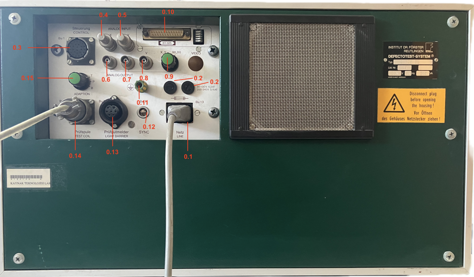
DEFECTOMAT F 2.825.07 Rear Panel
| Item | Description |
|---|---|
| 0.1 | Mains Socket, Bu 13 |
| 0.2 | Power supply fuse switch |
| 0.3 | Socket control, Bu 1 |
| 0.4 | Socket X, Analog Input |
| 0.5 | Socket Y, Analog Input |
| 0.6 | Socket X, Analog Output |
| 0.7 | Socket Y, Analog Output |
| 0.8 | Socket V, Analog Output |
| 0.9 | Changeover switch X, Y |
| 0.10 | Socket IEC-625 |
| 0.11 | Socket, ground |
| 0.12 | Socket, synchronization, Bu 7 |
| 0.13 | Socket, test piece sensor, Bu 6 |
| 0.14 | Socket, test coil, Bu 3 |
| 0.15 | Changeover switch, Adapter Facility |
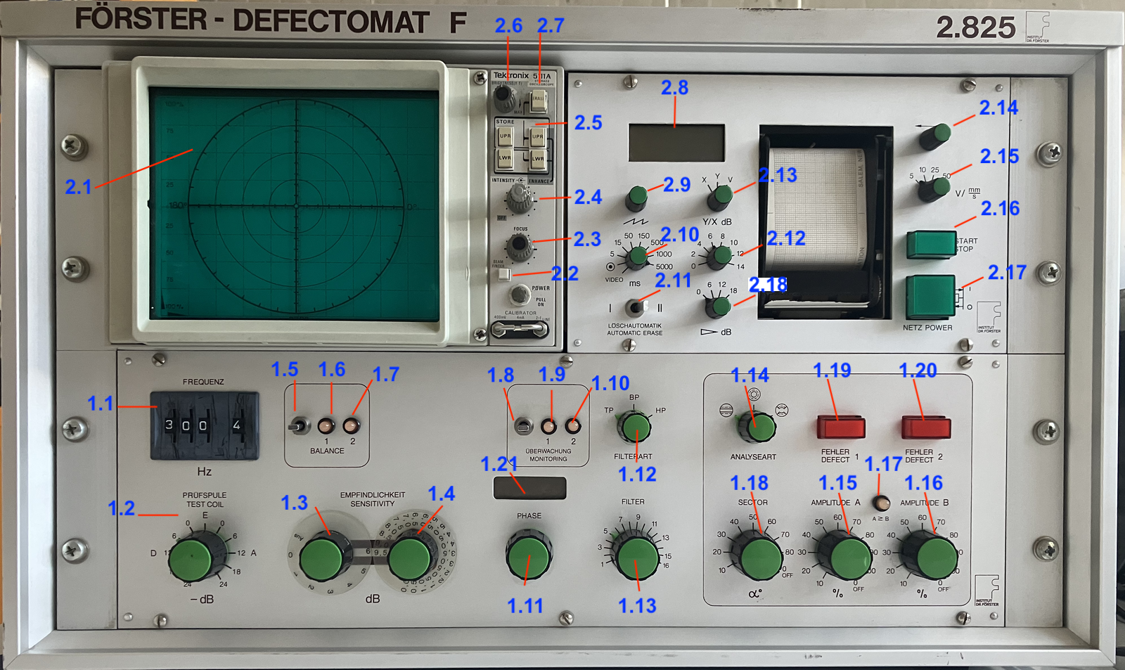
DEFECTOMAT F 2.825.07 Front Panel
| Item | Description | Item | Description |
|---|---|---|---|
| 1.1 | Frequency switch | 2.1 | Oscilloscope, display unit |
| 1.2 | Test coil knob | 2.2 | Beam finder |
| 1.3 | Sensitivity knob | 2.3 | Focus |
| 1.4 | Fine Sensitivity knob | 2.4 | Beam intensity |
| 1.5 | Compensation switch | 2.5 | Store buttons |
| 1.6 | Pilot lamp 1 | 2.6 | Brightness |
| 1.7 | Pilot lamp 1 | 2.7 | Erase button |
| 1.8 | Monitoring switch | 2.8 | Digital voltmeter |
| 1.9 | Monitoring lamp 1 | 2.9 | Time base fine control |
| 1.10 | Monitoring lamp 2 | 2.10 | Time base switch |
| 1.11 | Phase adjuster | 2.11 | Mode selector switch for automatic erase |
| 1.12 | Filter mode switch | 2.12 | Y/X Expansion switch |
| 1.13 | Filter frequency switch | 2.13 | Changeover switch X, Y, V |
| 1.14 | Evaluation mode switch | 2.14 | Recorder stylus position control |
| 1.15 | Switch for flaw threshold A | 2.15 | Speed changeover switch |
| 1.16 | Switch for flaw threshold B | 2.16 | Start/Stop pushbutton |
| 1.17 | Indicator lamb A greater then B | 2.17 | Power supply switch |
| 1.18 | Sector switch | 2.18 | Y/X Expansion switch, course |
| 1.19 | Flaw indicator lamp 1 | ||
| 1.20 | Flaw indicator lamp 2 | ||
| 1.21 | Digital display for phase |