Introduction
In this book, operating instructions for Eddy Current devices are presented. These devices are located at the KATAMER labs.
DEFECTOMAT F 2.825
The DEFECTOMAT F is the system for universal eddy-current testing. It can be used in the following main areas:
- Examination of specific tasks of eddy-current testing and measurement, e. g. flaw testing, materials sorting, coating thickness measurement, conductivity measurement ferrite content measurement, wall thickness measurement.
- Experimental determination of eddy-current testing parameters, optimizing of tester settings for automatic operation.
- Manual and semi-automatic component testing, e. g. in aircraft maintenance, nuclear energy, the chemical industry and general engineering.
Preparation and Connection
All connection sockets of the DEFECTOMAT F are located at the connection panel at the rear.
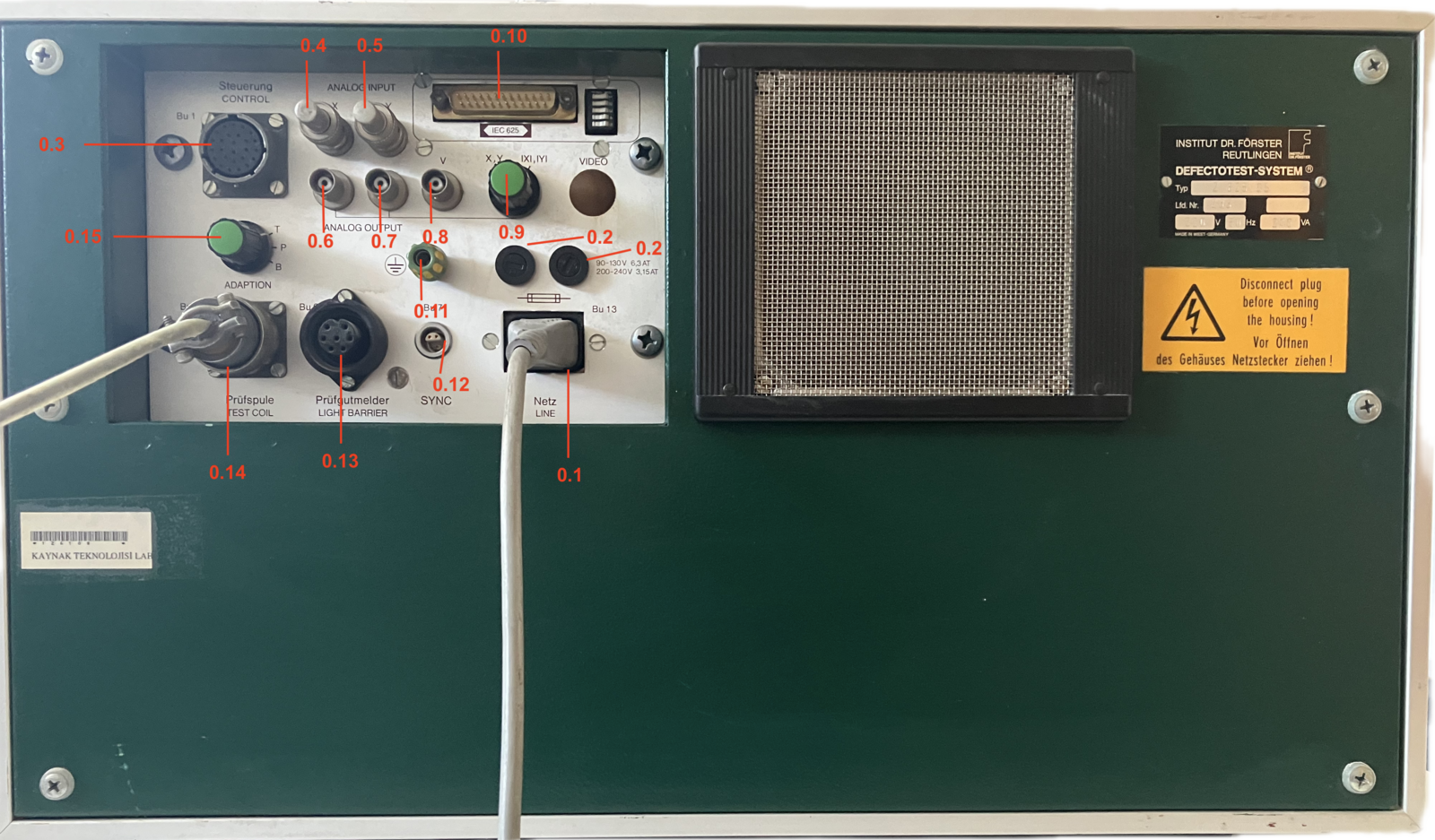
DEFECTOMAT F 2.825.07 Rear Panel
| Item | Description |
|---|---|
| 0.1 | Mains Socket, Bu 13 |
| 0.2 | Power supply fuse switch |
| 0.3 | Socket control, Bu 1 |
| 0.4 | Socket X, Analog Input |
| 0.5 | Socket Y, Analog Input |
| 0.6 | Socket X, Analog Output |
| 0.7 | Socket Y, Analog Output |
| 0.8 | Socket V, Analog Output |
| 0.9 | Changeover switch X, Y |
| 0.10 | Socket IEC-625 |
| 0.11 | Socket, ground |
| 0.12 | Socket, synchronization, Bu 7 |
| 0.13 | Socket, test piece sensor, Bu 6 |
| 0.14 | Socket, test coil, Bu 3 |
| 0.15 | Changeover switch, Adapter Facility |
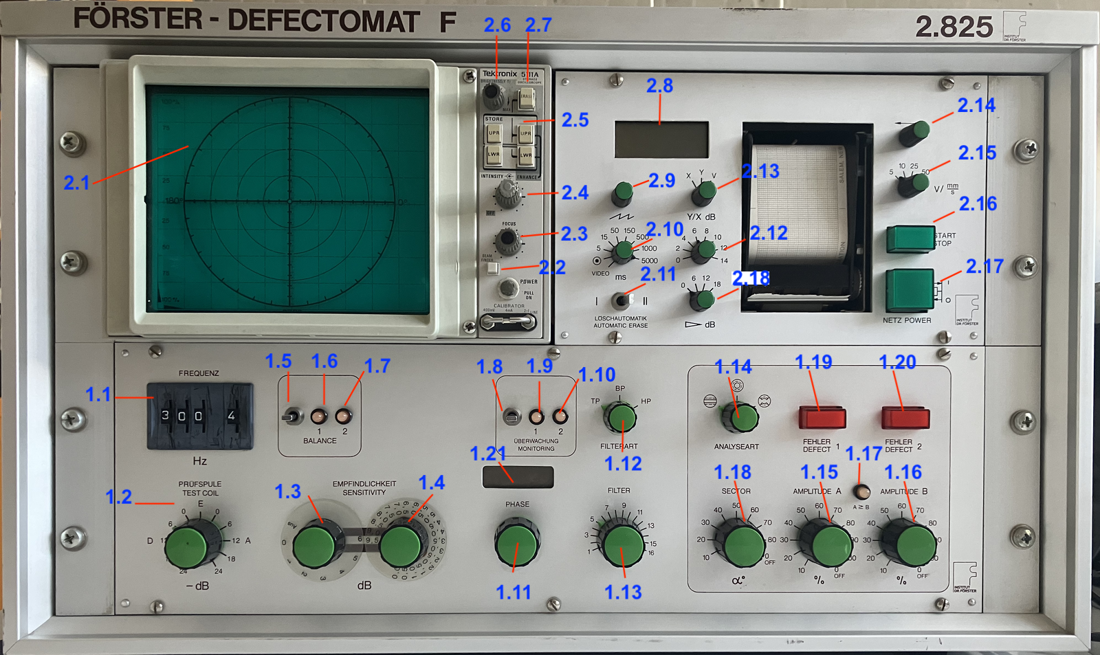
DEFECTOMAT F 2.825.07 Front Panel
| Item | Description | Item | Description |
|---|---|---|---|
| 1.1 | Frequency switch | 2.1 | Oscilloscope, display unit |
| 1.2 | Test coil knob | 2.2 | Beam finder |
| 1.3 | Sensitivity knob | 2.3 | Focus |
| 1.4 | Fine Sensitivity knob | 2.4 | Beam intensity |
| 1.5 | Compensation switch | 2.5 | Store buttons |
| 1.6 | Pilot lamp 1 | 2.6 | Brightness |
| 1.7 | Pilot lamp 1 | 2.7 | Erase button |
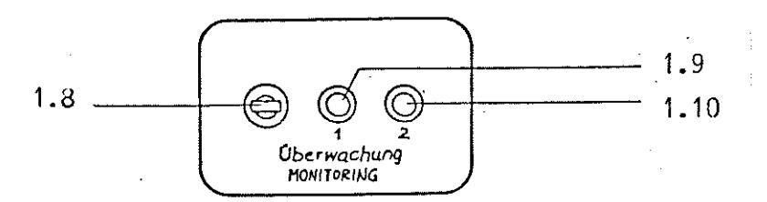
| 1.8 | Monitoring switch | 2.8 | Digital voltmeter |
| 1.9 | Monitoring lamp 1 | 2.9 | Time base fine control |
| 1.10 | Monitoring lamp 2 | 2.10 | Time base switch |
| 1.11 | Phase adjuster | 2.11 | Mode selector switch for automatic erase |
| 1.12 | Filter mode switch | 2.12 | Y/X Expansion switch |
| 1.13 | Filter frequency switch | 2.13 | Changeover switch X, Y, V |
| 1.14 | Evaluation mode switch | 2.14 | Recorder stylus position control |
| 1.15 | Switch for flaw threshold A | 2.15 | Speed changeover switch |
| 1.16 | Switch for flaw threshold B | 2.16 | Start/Stop pushbutton |
| 1.17 | Indicator lamb A greater then B | 2.17 | Power supply switch |
| 1.18 | Sector switch | 2.18 | Y/X Expansion switch, course |
| 1.19 | Flaw indicator lamp 1 | ||
| 1.20 | Flaw indicator lamp 2 | ||
| 1.21 | Digital display for phase |
Mains Connection
Mains Connection
The DEFECTOMAT F is set at the factory for operation at 220 V, 50 Hz. The permissible mains voltage tolerance is -20% to +10%. The unit must be connected to the mains power supply using a supplied, commercially available connecting lead via the mains connection Socket Bu 13 (Item 0.1), connected to a shockproof plug in accordance with DIN 49 441.
The mains connection socket complies with Standard CEE 22, Standard Sheet IV DIN 49 457.
Connection of Probes
Connection of Probes
The testing transmitters (test coils, scanning coils and hand-held rotating heads etc.) must be connected via a coil cable, possibly interconnecting an adapter at Socket 3 (Item 0.14) “test coil”.
The testing transmitters belonging to the DEFECTOTEST system are provided with a matching connecting plug. Please note the following detailed information if it is intended to connect other special-purpose testing transmitters, possibly self-manufactured testing transmitters.
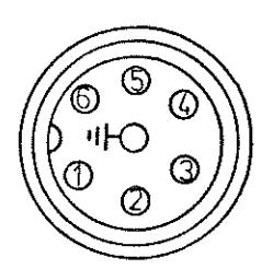
Socket 3 is a socket in accordance with Mil C 26 482, type PT 02 A 14-14S.
The matching mating plug has the designation PT 06E 14-15 P (SR).
Socket 3 has the following pin assignment:
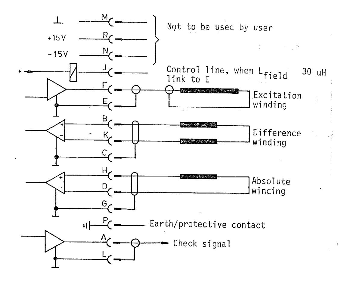
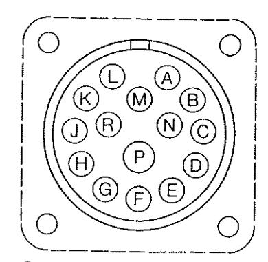
Tester (Socket PT O02 A-14-155)
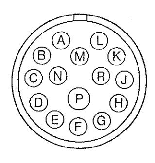
Test Coil (Plug PT O6A-14-15P (SR))
Test Piece Sensor
Test piece sensor
The DEFECTOMAT F incorporates a static signal gate in order to permit suppression of unwanted signals resulting from the leading or trailing end of the test object when testing separate items.
The test piece sensors required for operating this signal gate are connected via a test piece sensor cable to Socket 6 “test piece sensor” (Item 0.13).
The test channel of the DEFECTOMAT F can also be activated or deactivated via Socket 6, e.g. by means of a computer. If operating the system without a signal gate, the test piece sensors are not required. Socket 6 is a Socket 3107 manufactured by Messrs. Amphenol-Tuchel. The related plug is 3104-001 or an equivalent type. Socket 6 has the following pin assignment:
Tester
Test piece sensor
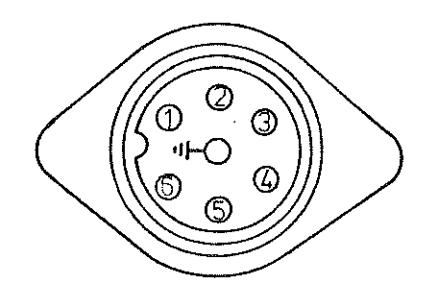
Socket T3107-000
Plug T3104-001
Looking on connection end
Ident-no. oo159
Ident-no. 003711
Synchronization
Synchronization
Pulses can be injected at Socket 7 “SYNC” (Item 0.12) for external synchronization of the signal display. Type 2.899.01-3001 is one of a number of suitable pulse transmitters. The ON threshold is 0.2 V ± 10 %, the OFF threshold 0.1 V ± 10 % and the input impedance 10 k Ω.
Socket 7 is a built-in Lemo socket Ra. 1303 TE. The related plug type is as follows: F 1303 TE. The socket has the following pin assignment:
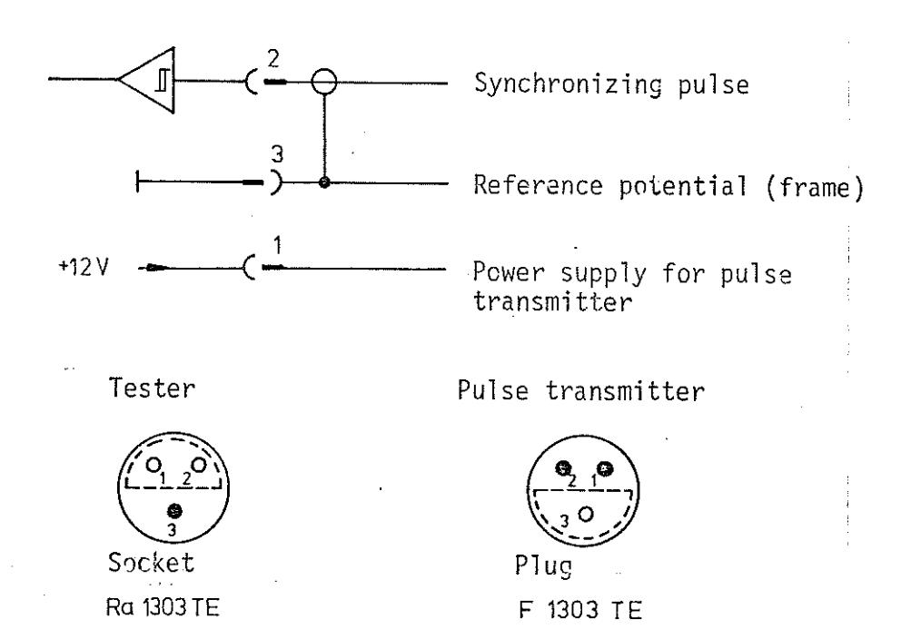
Looking on connection end
Ident-no. 009300
Ident-no. 009600
Note: If Socket “SYNC” is not used, the time base of the display unit is synchronized by material entry.
Analog Inputs and Outputs
Analog inputs and outputs
Inputs
Analog signals, e.g. from a magnetic tape device or a computer can be entered via digital/analog converters via Sockets Bu 4 “X” and Socket Bu 5 “Y” (Items 0.4 and 0.5). For this purpose, switch “test coil” must be set to position E.
The input sensitivity is ± 1 V for full CRT display ( ± 5 cm) with the sensitivity switches (Items 1.3 and 1.4) set to 20 dB. The amplitude of the injected signals can be modified at the sensitivity switches, the phase angle of the signals can be modified at the phase adjuster and the frequency spectrum can be modified at the switches for filter mode and filter frequency.
Outputs
External signal recording and/or processing devices (e.g. recorders, magnetic tape devices, oscilloscopes and computers etc.) can be connected to the analog output sockets X, Y and V (Items 0.6, 0.7 and 0.8).
The output voltages are ± 1 V for full CRT display ( ± 5 cm). The internal impedance is 600 Ohm in each case. The rectified magnitudes of the two signal components or the full, non-rectified horizontal and vertical components of the test signal are available at the Sockets “Y” and “X”, via changeover switches (Item 0.9). The amplitude of the test signal can be taped at Socket “V”.
All sockets for the analog signals comprise BNC Sockets in accordance with MIL C 39 012.
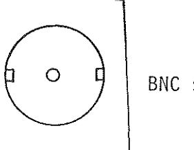
BNC sockets Ident-no. 001622
Control
Control
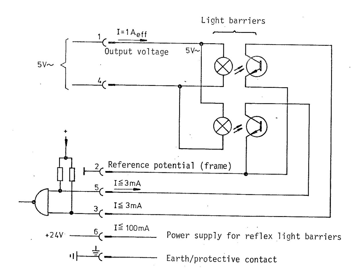
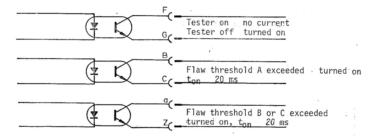
Signals required for recording, marking, sorting and data processing (via series-connected units) are issued continuously at Socket Bu 1 control (Item 0.3).
Socket Bu 1 supplies
- a flaw signal if flaw threshold A is exceeded
- a flaw signal if flaw threshold B is exceeded signaling the operating condition (signal gate) supply voltage for marking etc. (24 V DC).
The Socket is of type PT 02 A 16-26 S in accordance with Mil C 26 482. The matching plug is PT 06 A 16-26 P (SR).
Pin assignment of Bu 1:
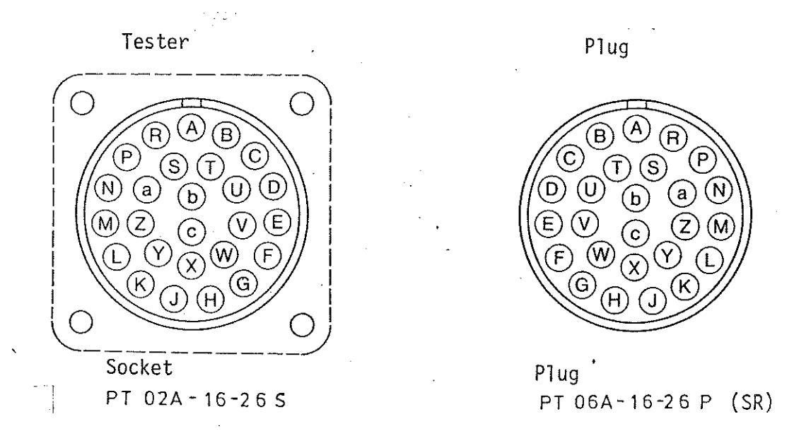
Looking.on connection end
Setting the Tester
Power supply switch
It is absolutely imperative that the instructions below be observed when switching on the tester for the first time or if the tester has been out of operation for a period exceeding 14 days.
Set the BRIGHTNESS control to fully clockwise position Depress the STORE button Set both power supply switches to “On”
After a short period, the screen becomes very bright. Operate the tester for five minutes with this setting. After this, ERASE can then be depressed or the tester can be operated in non-storage mode.
The DEFECTOMAT F can be switched on by depressing the power supply switch. The incorporated green pilot lamp than lights.
The display unit is switched on by pulling the power supply switch. This power switch is only operative if the power supply switch is depressed.
Frequency
Frequency switch (Item 1.1)
The test frequency is set at the frequency switch in accordance with the testing task. The setting range is:
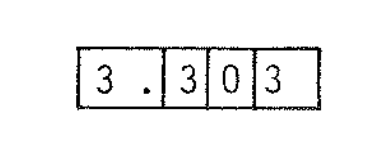
$1.00 \times 10^2$ - $9.99 \times 10^5$ Hz
The set frequency is displayed as a factor in the range 1.00 to 9.99 at the three left-hand levels of the frequency switch and as a base-10 exponent at the right-hand level of the frequency switch.
Example: 3.3 kHz = 3.30 x 10^3 Hz is displayed as
Test Coil Switch
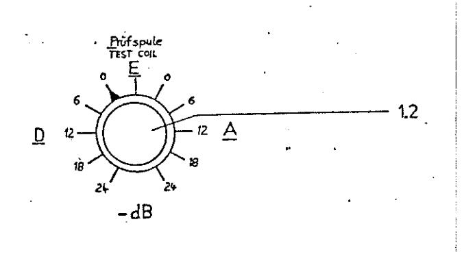
Test coil switch (Item 1.2}
The test coil switch can be used to switch either the input for differential windings (switch settings D) to the receiver or absolute windings of the test coils or probes to the receiver (switch settings A). In addition, the input signal can then be attenuated if the applied input voltage is too high (please also refer to Section 1.1.5).
Sensitivity Switches
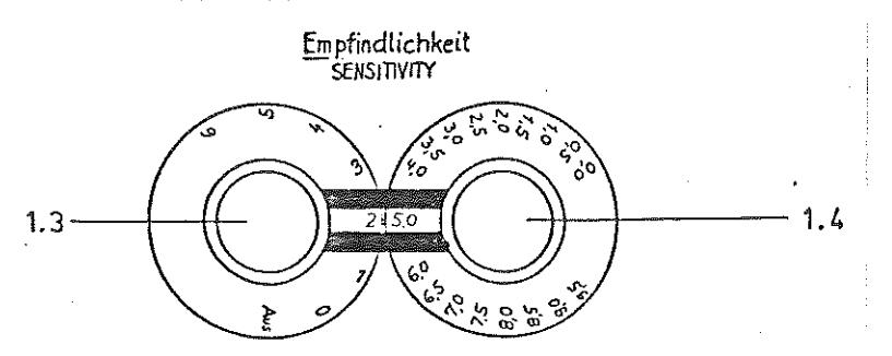
Sensitivity switches (Items 1.3 and 1.4)
The required sensitivity, i.e. the gain of the receiver unit, is set in dB at the sensitivity switches, coarse and fine. The gain variation range is 69.5 dB in stages of 0.5 dB. The displayed values are relative values.
Since the overall sensitivity is also determined by the primary current, frequency and coil inductance in addition to the receiver gain, display of the absolute gain values has been consciously dispensed with.
The mathematical relationship between sensitivity E, measured in dB, and the ratio of the output voltage to the input voltage is as follows:
$$ E(\text{dB}) = 20 \times \log \left(\frac{U_{\text{out}}}{U_{\text{in}}}\right) $$
Automatic Zero Compensation
Automatic Zero Compensation (Items 1.5, 1.6, 1.7)
Automatic compensation is initiated by depressing the compensation switch (Item 1.5), i.e. a countervoltage is added to the input voltage automatically until the value 0 is reached at the receiver output. Pilot lamp 1 (Item 1.6) lights for as long as compensation is operative. During this period, the input voltage must not be changed, i.e. the connected probe and the test object must not be moved or moved relatively to each other respectively. Automatic compensation is also initiated when switching over to filter mode TP (low-pass) (please also refer to Section 2.8).
The incorporated drift tracking facility is activated by setting the compensation switch to the upper position.
Tracking of the output voltage to 0 is essentially slower than is the case with compensation. The tracking speed is set at the factory to the highest speed yet can be varied internally in 7 stages by a total of 2! = 128,
During tracking, pilot lamp 1 lights continuously and pilot lamp 2 (Item 1.7) lights following the tracking rhythm which becomes increasingly slower as the 0 point is approached.
When switching over to drift tracking, automatic compensation (as above) is initiated initially.
If pilot lamp 2 lights continuoulsy, the tracking facility has reached its limit. The deviation is excessive.
Monitoring
Monitoring (Items 1.8, 1.9, 1.10)
Monitoring lamp 2 indicates blocking of the test channel. If monitoring lamp 2 is not lit, the test channel is operative. Section 1,3 describes the blocking facilities in greater detail.
Monitoring lamp 1 (Item 1.9) serves to indicate inadmissible operating conditions at the transmitter output = primary coil or at the receiver input = secondary coil.
The transmitter voltage must not exceed 10 V since this would otherwise overload the transmitter stage and trouble-free operation would thus no longer be guaranteed. If the transmitter voltage increases above this value, e.g. owing to interruption of the primary coil circuit or incorrect, unsuitable testing transmitters, monitoring lamp 1 lights.
If the monitoring switch (Item 1.8) is switched to upper position, the primary voltage is faded in in the form of a vertical line on the display. Full CRT display = 10 cm line corresponds to 10 V transmitter voltage.
In order to achieve proper functioning with the test coil switch (Item 1.2) set to operating mode D, the receiver voltage must remain below 90 mV and, in operating mode A, below 600 mV. Poorly adjusted, damaged or incorrectly connected testing transmitters, for instance, may cause these values to be exceeded. This is then also signaled by monitoring lamp 1 (Item 1.9).
If the monitoring switch (Item 1.8) is set to lower position, the full, uncompensated input voltage is displayed on the CRT as a dot. The 5 cm circle corresponds to the above-mentioned limit values,