Analog inputs and outputs
Inputs
Analog signals, e.g. from a magnetic tape device or a computer can be entered via digital/analog converters via Sockets Bu 4 “X” and Socket Bu 5 “Y” (Items 0.4 and 0.5). For this purpose, switch “test coil” must be set to position E.
The input sensitivity is ± 1 V for full CRT display ( ± 5 cm) with the sensitivity switches (Items 1.3 and 1.4) set to 20 dB. The amplitude of the injected signals can be modified at the sensitivity switches, the phase angle of the signals can be modified at the phase adjuster and the frequency spectrum can be modified at the switches for filter mode and filter frequency.
Outputs
External signal recording and/or processing devices (e.g. recorders, magnetic tape devices, oscilloscopes and computers etc.) can be connected to the analog output sockets X, Y and V (Items 0.6, 0.7 and 0.8).
The output voltages are ± 1 V for full CRT display ( ± 5 cm). The internal impedance is 600 Ohm in each case. The rectified magnitudes of the two signal components or the full, non-rectified horizontal and vertical components of the test signal are available at the Sockets “Y” and “X”, via changeover switches (Item 0.9). The amplitude of the test signal can be taped at Socket “V”.
All sockets for the analog signals comprise BNC Sockets in accordance with MIL C 39 012.
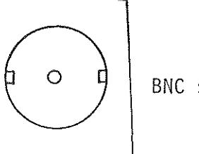
BNC sockets Ident-no. 001622