FILPRO
The most flexible and powerful Microwave and RF Filter and Multiplexer Design
Software
Prof. Dr. Nevzat Yildirim, E-Mail: nyil@metu.edu.tr
(Presented at the workshop "State of the Art Filter Design
using EM and Circuit Simulation Techniques" in MTT-S'97, Denver,
Colorado, USA)
FILPRO at the MTT-S'97, Denver
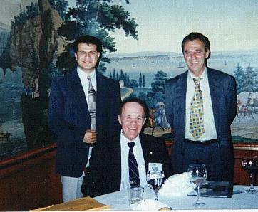
Two of the FILPRO creators, Dr.
Nevzat Yildirim (right)and his assistant Mehmet Karaaslan (left) with Dr.
Richard Snyder (sitting) of RS MICROWAVE COMPANY at MTT-S'97 Symposium,
Denver, Colorado where FILPRO is also presented in the workshop entitled
"State of the Art Filter Design Using EM and Circuit Simulation
Techniques
FILPRO at the MTT-S'99, Los Angeles
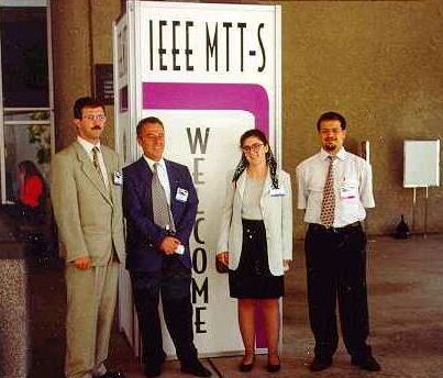
Four of the FILPRO creators
(left-to-right), Yakup Sen, Nevzat Yildirim, Ozlem Sen and
Mehmet Karaaslan at MTT-S'99 Symposium,
Los Angeles, California where some CQ-CT applications of FILPRO are
presented as a paper
FILPRO at the MTT-S 2000, Boston
With Dieter Pelz of RFS Australia, a distant contributor of Filpro
FILPRO at the MTT-S 2004, Forth Worth, Texas
With Mustafa Akkul of Filtronics-England, another contributor of Filpro
FILPRO at the MTT-S 2004, Forth Worth
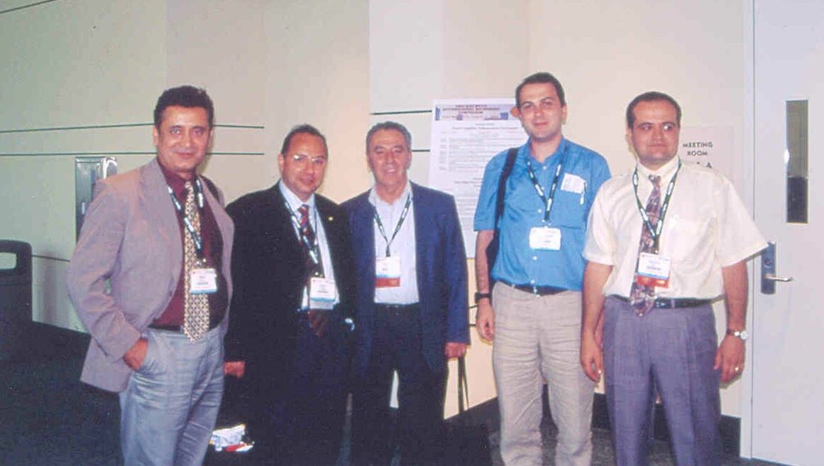
Turkish Team at MTT-S 2004
Filpro is an extremely flexible software package developed in a novel
approach for fast synthesis,
circuit transformation and analysis of
lumped and distributed element filtering, multiplexing, matching and
coupling structures.
The distinguishing characteristics of the approach is modularity of all
design steps. Almost all the synthesis and circuit transformation
techniques available in literature are programmed as independent
modules and placed in different toolboxes (menus). A typical design
procedure is formed simply by selecting the necessary techniques from the
toolboxes and linking them. This approach provides great flexibility in
reaching almost any filter seen in literature in a fast and easy way using
a single software. All the steps are under the control of designer,
giving the opportunity to observe effects of various circuit
transformations and approximations on response instantly. It is aimed at
the most complex lumped and distributed filters. The well known,
classical filters can be designed just as side products.
- The software is initially developed as a teaching and self learning aid.
Therefore it can be used by teachers and students in undergraduate or
graduate filter design or microwave courses.
- The software can also be used by novice or non-specialist engineers for
either self learning or for fast survey of alternative solutions in
engineering project applications.
- The software is elaborated through many practical design applications
in industry (e.g., M/A-COM Corporate R. D., Lowell, Mass., USA- RS Microwave
Company,
New Jersey, USA- Aselsan Military Electronics Ind. Inc. Ankara, Turkey-
RFS/ALCATEL of Australia- MURATA Mfg. Co. of Japan), Saab-Ericsson Space,
Sweden, Motorola, Indiana, U.S.A., Merrimac Ind., U.S.A., TRW,
California, U.S.A, to name a few.
Therefore it can be used to solve tough real life filter design problems.
- The software is developed in an academic environment, through M. Sc.
and Ph. D. Theses of many students. Therefore it can be used for advanced
academic or industrial research problems. The tedious and complex nature
of circuit transformations needed in advanced filter design problems form
the main barrier blocking the views of researchers for finding out new
solutions. In Filpro, these barriers are lowered by programming the
complex circuit transformations in a modular manner, so that the targeted
structures are reached quickly, enabling fast survey of alternative
solutions.
- The software can be enlarged to cover new types of problems simply by
adding new modules.
In a typical filter design problem Filpro offers the following
capabilities in different stages:
1.SYNTHESIS STAGE:
A targeted filter is designed by selecting a proper technique
from the
synthesis menu containing diverse filter design techniques like
Exact Synthesis, Synthesis from Built in LC Prototypes, Synthesis
using Prototypes with Inverters, Synthesis from User Defined Prototypes,
Cross-Coupled filters, Diplexers, Dual Band Filters, etc.
- Exact Synthesis option can be used to synthesize lumped or
Commensurate length distributed element LP, HP and BP filters
with maximally flat or equiripple passband, general stopband filters.
Distributed element filters include contributing unit elements
and finite transmission zeros. Response is shaped by placing transmission
zeros and then tuning them. This stage has the following features:
- Shaping up of response is displayed while transmission zeros are
placed.
- Response can be adjusted by Tune A Finite Transmission
Zero command.
- Elements can be extracted using Manual Extraction or
Standard Automatic Extraction or Macro Automatic
Extraction features.
- Tune A Finite Transmission Zero and Extract command eases
iterative searches in the synthesis stage.
- Design By Built in LC Prototype option can be used to design
lumped and distributed element LP, HP, BP and BS filters with Chebyshev,
Butterworth and Generalized Chebyshev responses. For lumped element
bandpass filters, 15 classical alternative realizations are instantly
available. In
distributed element filters redundant unit elements can be inserted
using Kuroda Transformations. Cohn's inverter approach can be
applied on
these filters to produce all-series-resonator or all-shunt-resonator
structures. Numerous alternative equivalent filters can be produced
by replacing ideal inverters with practical inverters and
replacing resonators by desired lumped-distributed practical equivalents.
- Design By Prototype with Inverters approach can be used for
quick design of symmetric LP, HP, BP or BS filters involving ideal
inverters. Ideal inverters are then
replaced by practical circuits selected from a huge library. This
approach enables one to design some filters in a quicker way. One
push button replacement of ideal inverters with practical ones provides a
great flexibility in search and realization of alternative equivalent
practical filters.
- User Defined Prototype option is placed into Filpro to
enable the
designer to use the lowpass prototype tables found elsewhere (texbooks,
handbooks, papers, etc.) which are not available in Filpro.
External prototype circuits are formed by inserting elements one by one
and saved for use in Filpro. The prototypes may also be prepared by
the other techniques of Filpro, for example using
Synthesis approach and saved. Then these prototypes may be
used for example to design channel filters of multiplexers, or
elliptic bandstop filters, etc.
- Design By Inserting Elements option allows to configure a
desired cascaded element circuit by inserting elements. In this mode
Filpro works as a fast and easy to use network analyzer supported by a
huge arsenal of circuit transformations. Application of this
command displays the source and load resistances. Elements are inserted
simply using Insert command which displays the element library for
selection. One click places the element into any position in the circuit
indicated by the circuit cursor. Element library includes over hundred
elements characterized by their ABCD parameters. Element library can be
enlarged if necessary, by the programmers, as desired by the customers.
Externally measured or characterized one and two port elements
(characterized though S parameters) may also be inserted. This option is
used very effectively by the students in Microwaves courses and
laboratories as a very handy "soft network analyzer".
- LP-HP Diplexer command is used to design singly terminated
lumped and distributed element, maximally flat or Chebyshev LP-HP
diplexers with user specified cross-over loss.
Singly terminated LP-HP Diplexers with finite transmission zeros, singly
terminated BP-BS and BP-BP multiplexers with or without finite
transmission zeros are formed by first designing the channel filters and
combining them in parallel. Doubly terminated parallel BP, Lowpass-Highpass
and manifold type multiplexers are also formed, analyzed, tuned and
optimized by first designing the individual channel filters and combining
them. Switched multiplexer type structures may be formed using
branch line directional couplers to couple the channels to the manifold
line as
shunt filter channels. Series connection of the channel filters to the
manifold line may also be formed using coupled lines with one port of
the second line being short circuited.
- Dual Passband Filter option uses two quasi-lowpass
(impedance transforming) filters (previously designed and saved) to form
a single bandpass filter with two passbands.
- The command Symmetric Cross Coupled Circuits can be used for
Analysis and tuning of symmetric coupled structures like symmetric
cross coupled filters, branchline directional couplers, parallel coupled
line directional couplers, rat race hybrids. The even and odd mode half
approach is used for analysis of such structures.
WAVEGUIDE FILTERS
- Synthesis of direct coupled evanecent mode or propagating mode rectangular waveguide
filters with or without ridges/fins are available.
CROSS-COUPLED FILTERS
Synthesis of Cascaded Triplet (CT), Cascaded Quadruplet
(CQ) and Generalized Cascaded Quadruplet (GCQ) (Quadruplets
with diagonal cross-coupling) filters by pole placement using the
classical cascade synthesis approach are now available, including
linear phase options.
Design of higher order N-tuplet filters (Quintuplet, Sixtuplet, Seventuplet,
eighttuplet, ninetuplet and tentuplet) are available including
linear phase options with inverter type coupling elements.
2.CIRCUIT TRANSFORMATIONS STAGE:
Synthesized filters usually have undesirable topologies with unrealizable
element values. In Filpro these circuits are transformed into desired
toplogies with realizable element values by applying a set of circuit
transformations selected from the Circuit Transformations
toolboxes (menus). Macro programming feature speeds up the design if the
number of circuit transformations are excessive. A huge number of circuit
transformations are have been developed and placed into Filpro for
designing almost all the classical and novel filters seen in
literature.
The circuit appears on the screen automatically after the synthesis
stage with a textbook type schematics. Elements of circuits are
pointed by a moving cursor. Parameters of pointed elements are
displayed automatically. The whole circuit can also be moved to right
or left if the number of elements is large. The transformations are
applied by pointing the element(s) with the circuit cursor and
clicking the circuit transformation command selected from the menu.
Some of the circuit transformations available in Filpro are as
follows:
- Inserting, deleting, splitting, combining, exchanging, copying
and pasting elements. Shifting transformers to anywhere in the circuit.
- Conversion of ideal lossless elements into practical elements involving
all parasitics. Q-adjustment of all elements with a single keystroke.
- Coupled Coil transformations enabling conversions among coupled
coils, tapped coils, Pi-Tee-L sections and ideal transformer sections.
- A variety of Impedance Matching Circuits are available for
narrowband matching of real or complex loads or for adjustment of
source-load resistance or for adjustment of element values of circuits.
- Dumbbell transformation enables conversion of lumped element bandpass
filters into Dumbbell structure.
- Replacement of single L or single C by LC resonators and replacement
of LC resonators by various equivalents enable
designers to make numerous tricky modifications on filter responses,
including conversion of Chebyshev bandpass filter into an elliptic
bandpass filter.
- Conversion of lumped and distributed elements into their
constant reactance equivalents at user set frequencies or replacement of
constant reactances by their lumped L, C, LC, OC Stub or SC Stub
equivalents provide great flexibilty in obtaining approximate equivalent
circuits.
- Replacement of lumped LC resonators with lumped, distributed or mixed
equivalents (found through Reactance Slope Parameter approach or by
equating them at passband edges) enables designers to carry out Cohn
Synthesis Techniques in the most versatile manner, including
transformation of Chebyshev filters into elliptic filters.
- Kuroda and Kuroda-Levy identities and with multiple Kuroda
transformations programmed as a single command simplifies design of many
complex bandpass filter structures greatly. For example, all the
classical and some novel Minnis Class filters can be designed by a number
of keystrokes.
- Conversion of stub and unit element combinations into their parallel
coupled line equivalents of almost all kinds, including asymmetric and
inhomogeneous coupled lines (with OC, SC, stub or capacitor loading at
unused ports) quickens design of coupled line filters a lot.
- Conversion of some stub sections into two or four step resonators
with a single keystroke enables designers to cumbersome
analytical transformation stages.
- p-Transform (Half Angle transform) can be used to convert
commensurate line highpass filters into bandpass filter structures with
halved stub lengths.
- Hairpin Line transformations enable the design of hairpin filters
from half wave parallel coupled line filters.
- Changing dielectric constant of single lines by keeping their
electrical lengths constant eases analysis of stub-transmission line
filters. Changing even and odd mode dielectric constants of symmetric or
asymmetric coupled lines enables conversion from homogeneous medium to
inhomogeneous medium easily. The effects of such imperfections can be
analyzed instantly.
- Norton transformations on single and multiple elements and
Multiple Norton transformations (Geffe, Inverse Geffe, Colin and Humpherys
transformations) enables formation of numerous
alternative realizable-desirable topologies in lumped and distributed
filters. They can also be used for decreasing number of inductors.
- Pi-Tee-L transformations with single keystrokes are very effective
tools in searching alternative realizable filter structures. Capacitance
Matrix Transformations are special forms of Pi-Tee-L transformations. For
example it is staright forward to get equal shunt inductor combline
filters or equal shunt inductor CT filters.
- Replacement of transmission line pieces by Pi or Tee, distributed or
lumped equivalents form handy tools for finding alternative equivalent
structures.
- Replacement of some elements by their transmission line equivalents,
replacement of distributed elements by their lumped equivalents,
replacement of some elements by their shunt open circuit stub
equivalents are frequently needed transformations which can be carried
out instantly in Filpro.
- There are many transformations involving inverters:
- Replacement of an element by its ideal inverter equivalent.
- Replacement of an ideal inverter by a practical inverter selected
from a huge library.
- Insertion of ideal inverter into a circuit.
- Scaling terminations of a circuit by adjusting or inserting inverters.
- Inserting inverters at source and load ends to scle up-down the
impedance level of the circuit. These end inverters may then be replaced
by Pi or inverted-L sections made up of lumped capacitors, lumped
inductors, SC or OC stubs.
- Scaling element values by adjusting inverters on the two sides.
- Scaling inverters to produce transformers or to equate elements on
the two sides of an inverter.
- Absorbing transformers by inverters.
- The commands for conversion of some circuit elements into evanescent
waveguide forms and vice versa, scaling of a filter for the selected
evanescent waveguide cross-sectional dimensions ease design of Evanescent
Mode Waveguide filters (including cross-coupled filters) a lot.
- It is possible to find dual of a circuit, symmetrizing a
circuit, reversing the input and output of displayed circuit,
renormalizing the circuit with respect to new terminations, appending a
previously saved circuit to the displayed circuit.
- It is possible to insert an externally measured or characterized two
port (through S-parameters).
- Inserting a previously designed filter into anywhere in the displayed
filter in shunt enables formation of a variety of multiplexers, like
parallel bandpass, LP-HP and manifold multiplexers.
Cascaded Triplet (CT) filters are used to place finite transmission
zeros
in lower and upper stopbands independently of each other. Such filters
were designed using Cross-coupled filter synthesis approach.With Filpro,
it is now possible to synthesize them by the classical cascade synthesis
approach with pole placement and using a single command to transform it
to a cascaded triplet form.
Cascaded Quadruplet (CQ) filters are formed by cascading sections
termed as Quadruplets (four coupled resonators). Such sections place
finite transmission zeros on both sides of the passband in a
geometrically symmetric manner. Till now, they were designed using
cross-coupled filter synthesis approach and "Rotations". With Filpro,
it is now possible to synthesize them using the classical cascade
synthesis approach and a simple circuit transformation command, "Convert
to CQ". If necessary, one or more of the quadruplets can be made to create a
SIGMA AXIS TRANSMISSION ZERO to approximate constant delay about
passband center.
Generalized Cascaded Quadruplet (GCQ) filters are formed by cascading
sections termed as Generalized Quadruplets (four coupled resonators
including a diagonal cross-coupling). Such sections can
place finite transmission zeros on both sides of the passband in
asymmetric manner.
Cascaded Quadruplet elements may also be used to create a single finite transmission zero on any side of the passband. This approach avoids the diagonal cross-couplings of GCQ and CT sections.
Arbitrary CT, CQ and GCQ sections may be cascaded(CQ) to form
diverse topologies to get different filter characteristics, avoiding the
practical difficulties of Canonical Cross-coupled filters (filters with
input-output on the same side and having many vertical and diagonal
cross-couplings).
With these tools, the unbearably tedious circuit transformations are
transformed into a one or several push button manipulations, easing the
life of designer a lot. With these barriers eliminated, it is now much
easier and faster to search for the alternative equivalent circuits. It
is left to the imagination of the designer to discover new solutions. The
design process is splitted into a large number of command steps, each
step being under the control of the designer. Thus, the effect of each
transformation or approximation on response is instantly observed.
The state of the art in filter synthesis, design and implementation are
tracked closely simply by adding new modules into Filpro. It is an open
ended, extremely adaptive software, undergoing continuous modifications
after each academic or industrial applicaton.
3.ANALYSIS TOOLS:
- The resulting circuits can be analyzed using
Insertion Loss, Return Loss, Insertion Phase,
Group Delay and Smith Chart plots. Smith Chart also
displays S11, Zin, Yin and VSWR.
- Markers and Delta Markers are available.
- Zooming on vertical and horizontal axes are available.
- Reference lines can be placed on insertion and return loss
response to form Brick Walls.
- Sensitivity Analysis command can be used to asses sensitivity
of response to variations in element values.
- Tune Element command can be used for trimming response or manual
optimization of the circuit.
- Multiplexer command is used to display insertion loss
responses of all channels simultaneously. This command is also used for
tuning elements of channel filters while observing their insertion loss.
- Monte Carlo, Worst Case and Yield Analysis tools
are also available to asses tolerance effects. They work together with
brick walls specified by the user.
- The command Best Case is a very handy Local Optimizer
working together with Brick Walls placed on return loss only. Software first
makes a Monte Carlo search with user selectable elements and
element value percentage deviations to find a circuit with return loss
response satisfying the brick wall constraints, set loosely at the
beginning. Then return loss level is increased by user set increments
and new search starts with decreased element deviations. It is a very
effective, user directed adaptive local optimization strategy. It may
also be used as global random search optimizer by allowing large
deviations in element values together with loose initial return loss
constraints.
WHAT CAN BE DESIGNED?
The software is capable of designing most of the practical filtering,
multiplexing, matching and coupling circuits, from old classical filters
to modern, miniature circuits. Owing to modularity, new filter types can
also be handled by adding the necessary modules. Some of the filter types
that the present version of Filpro can handle are listed as follows:
LUMPED ELEMENT LP, HP, BS and BP FILTERS (singly or doubly
terminated):
- Lumped Element Lowpass Filters:
- Synthesis approach by pole placement for designing symmetric or
antimetric filters with any number of transmission zeros at infinity or
at finite frequencies, including impedance transforming filters.
Equiripple or maximally flat passband, general stopband. Singly or doubly
terminated.
- Built in LC Prototype approach for Chebyshev, Butterworth
and
Generalized Chebyshev filters with one or three transmission zeros at
infinity.
- User defined prototype approach for filters can be used to design
filters whose prototypes are not available in Filpro. Some lowpass
prototypes may be prepared by the user using Synthesis approach and then
saved for use with User Defined Prototype approach.
- Lumped Element highpass Filters:
- Synthesis approach by pole placement for designing symmetric or
antimetric highpass filters with any number of transmission zeros at
zero or at finite frequencies. Equiripple or maximally flat passband,
general stopband. Singly or doubly terminated.
- Built in LC Prototype approach for Chebyshev, Butterworth and
Generalized Chebyshev highpass filters with one or three transmission
zeros at zero.
- User defined prototype approach for filters not available in Filpro.
- Coupled Coil realizations of diverse kinds.
- Wideband bandpass filters as quasi-highpass filters to overcome
parasitic capacitances of shunt inductors.
- Lumped Element bandstop Filters:
- Built in LC Prototype approach for Butterworth, Chebyshev and
Generalized Chebyshev bandstop filters.
- User Defined Prototype Approach for synthesizing elliptic
bandstop filters. Elliptic lowpass prototype is prepared using
Synthesis approach and saved to be used as the prototype in User
Defined Prototype approach.
- Design By Prototype with Inverters approach for designing
lowpass, highpass and bandpass filters with a notch in their passband
- Lumped Element bandpass Filters:
- Synthesis approach for symmetric or antimetric filters with any
number of finite transmission zeros at zero, infinity and finite
frequencies. Equiripple or maximally flat passband, general stopband.
Singly or doubly terminated.
- With finite transmission zeros shared between lower and upper
stopband, or all in one stopband.
- With all filter crunching tools to reach realizable topologies and
element values.
- Including all alternative equivalent structures (series inductive or
capacitive coupling, shunt inductive or capacitive coupling, filters with
coupled coils, etc.).
- With circuit transformations for minimizing number of inductors.
- With circuit transformations for impedance matching at source and
load ends.
- Built in LC Prototype approach for Butterworth, Chebyshev and
Generalized Chebyshev bandpass filters. 13 ready filter topologies are
available for Chebyshev and Butterworth cases. Built in LC Prototype
approach can also be used to produce filters with all series or all
shunt resonators separated by ideal inverters.
- Prototype with Inverters approach is formulated for
quick design of symmetric Chebyshev filters with all series or all shunt
resonators separated by ideal inverters
- The filters involving ideal inverters and resonators can be
converted into many different forms by replacing the inverters and
resonators with their diverse practical equivalents using commands
"Replace Ideal Inverter By/.." and "Replace Resonator By /.."
commands (Cohn-Matthaei Approach).
DISTRIBUTED ELEMENT LP, HP, BS and BP FILTERS (singly or doubly
terminated):
Commensurate linelength distributed element filters can be synthesized
using the same techniques as the lumped element filters described above.
In these approaches, besides specifying the passband edge frequencies
and passband ripple, user is also asked to specify the quarter wavelength
frequency (fq) which sets the length of stubs or unit elements. Line or
stub length is quarter wavelength long (90 degrees) at that frequency.
If necessary, the circuit can be transformed into non-commensurate forms
with mixed lumped and distributed elements using various circuit
transformations.
Synthesis approach is used to design
singly or doubly terminated, maximally flat or equiripple passband
general stopband filters with or without contributing unit elements
through pole placement. Response is shaped first by placing the
transmission zeros and then adjusting positions of finite transmission
zeros. Elements can be extracted automatically, if the filter is a
standard one, or by extracting each transmission zero in the order set by
the designer or through Macro Auto Extract mode, if the element
extraction procedure was carried out in a previous design.
Design By Built-in LC Prototype approach can be used to
design All-Stub Chebysev, Butterworth and Generalized Chebyshev filters
(without contributing unit elements). Redundant unit elements can be
inserted using Kuroda identities. Inverters and various other circuit
transformations can be used to convert unrealizable stubs into
realizable stub or transmission line forms.
Design By Prototype with Inverters approach can be used for
quick design of symmetric Chebyshev filters involving only series or only
shunt elements separated by ideal inverters.
Design By User Defined Prototype approach can be used to make
use of lowpass prototypes not readily available in Filpro.
- Distributed Element Lowpass/Bandstop Filters:
Commensurate or noncommensurate lowpass filters with or
without contributing unit elements and with or without finite
transmission zeros. Realizations utilizing unit elements, shunt OC stubs,
shunt stepped stubs and various coupled lines. Stopband width adjustment by
selecting proper quarter wavelength frequency. Realization of finite
transmission zeros using stepped stubs. Various special coupled line
realizations for wide stopband and narrow stopband filters. Single
keystroke conversions into Spur Line, stub loaded coupled lines, etc.
- Distributed Element Highpass Filters:
- Open circuited half wavelength parallel coupled line filters.
- Wideband open circuited parallel coupled line filters with
contributing unit elements (Minnis type parallel coupled line filters).
- Short circuited half wavelength parallel coupled line filters.
- Interdigital filters.
- Short circuited line+unit filters.
- Hairpin filters.
- Tapped hairpin filters.
- Elliptic (LaTourette type) highpass filters with open circuited coupled
lines and stepped shunt stubs.
- Wideband highpass filters with multiple transmission zeros at f=0.
- Digital Elliptic filters.
- Synthesis of multiple step quarter wavelength impedance transformers as
All-Unit Element highpass filters.
- Distributed Element Bandpass Filters:
- Cohn-Matthaei approach for Inverter+Resonator filters (End Coupled
Line filters, Stepped Resonator Parallel coupled Line Filters, Elliptic
filters).
- Combline filters, Tapped Combline filters, stepped combline
filters, Miniature Block Dielectric Combline filters.
- Capacitively loaded line filters.
- All Unit Element miniature stepped impedance transformers (short line
transformers).
- Evanescent Waveguide bandpass filters.
- Minnis Type filters:Class-A, B, C, D, E, F and mixed Class-AE, etc.
- Broadband bandpass filters with contributing unit elements and
multiple transmission zeros at zero and infinity.
CROSS-COUPLED FILTERS:
- Symmetric Canonic n-cross-coupled linear phase filter design
using the available lowpass prototype tables.
- Levy's filter with single cross-coupling and single transmission
zero on real or imaginary axis of s-plane.
- Symmetric Selective Linear Phase Filters with double cross-coupling
having one transmission zero on real axis and one transmission zero on
imaginary axis.
- Cascaded Triplet (CT), Cascaded Quadruplet (CQ), Generalized
Cascaded Quadruplet (GCQ) and mixed CT-CQ-GCQ filters of any order by pole
placement to produce symmetric or asymmetric responses.
- Design of asymmetric canonic n-cross-coupled filters with vertical and
diagonal cross-couplings by pole placement is in preparation- as a
separate software.
MULTIPLEXERS
- Automatic design of singly terminated Chebyshev and Butterworth LP-HP
diplexers with user specified cross-over loss.
- Design of singly terminated elliptic LP-HP diplexers using lowpass
prototypes.
- Design of singly terminated BP-BS diplexers.
- Design of singly terminated BP-BP parallel diplexers and multiplexers.
- Analsis and Design of doubly terminated parallel bandpass multiplexers
through tuning and optimization, Combline multiplexer as example.
- Analysis and Design of doubly terminated lowpass-highpass multiplexers
through tuning and optimization.
- Analysis of manifold multiplexers (possibility of designing by tuning
and optimization).
- Design and analysis of switched multiplexers. Switchable channels can
be connected to the main input-output lines through branch line
directional couplers or through coupled lines with second line shorted at
one end.
IMPEDANCE TRANSFORMING BANDPASS FILTERS
- Narrowband Pi-Tee-L-Gamma type impedance matching circuit design
between resistive or complex terminations, including resistive Pi and Tee
attenuators.
- Special impedance matching sections for narrow and medium band
filters, including various practical inverters.
- All Unit Element Highpass Filters as Impedance Transformers (Quarter
Wavelength Transformers).
- All Unit Element Bandpass Filters as Impedance Transformers (Short
Line Matching).
- Highpass Filters with N-unit elements and a single SC stub as
impedance transformer.
- Bandpass filters with N-unit Elements and OC-SC Stubs as impedance
transfomers.
- Exponential Lines as Impedance Transformers.
IMPEDANCE TRANSFORMING DUAL PASSBAND FILTERS
- Two impedance Transforming quasi lowpass (bandpass) filters are used
to design a single filter with two matching passbands (Dual Band Matching).
IMPEDANCE TRANSFORMING BRANCHLINE COUPLERS
- Analysis and tuning of Impedance Transforming Branch Line Directional
Couplers with Two and Three Branches as examples.
TO BE CONTINUED!
MANUAL of FILPRO


