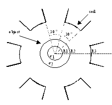
Fig.1. Discrete Coil EIT Configuration
 DISCRETE
COIL INDUCED CURRENT
DISCRETE
COIL INDUCED CURRENT
Abstract: A discrete coil induced current imaging system
is proposed. The solution methodology of the forward
problem of this system is explained. For concentric inhomogeneity problem,
optimum coil currents that maximize
the distinguishability are obtained.
I. INTRODUCTION
Electrical Impedance Tomography (EIT) is an imaging technique, which
distinguishes the conductivity differences
of tissues [1]. In EIT, current is injected throug 16-32 electrodes
and measurement of voltage along the boundary
of the object helps determine the image. Induced current EIT works
with the same principles, the main difference
being the induction of the current using a coil located outside the
object. In this work, a discrete coil induced
current system is proposed and analyzed. Optimum currents for best
distinguishability [3] are also reported.
Fig.1. Discrete Coil EIT Configuration
II. DISCRETE COIL INDUCED CURRENT EIT
In EIT, independent measurements are obtained by changing the positions
of the injection electrodes or by changing
the location of the coil [1,2]. Induced current in the object
can be controlled efficiently using the discrete coil
configuration shown in Fig.1 and by changing the individual coil currents.
III. METHOD OF ANALYSIS
The problem of Fig.1 can be solved easily using quasi-static assumption
and neglecting the displacement field in the
object. As a result, electric potential can be found using only
the Fourier coefficients of the normal component of the
magnetic vector potential along the boundary of the object. Each coil
current is assumed unity and the solution is
expressed as a matrix equation using Fourier coefficients. Forward
problem solution for any coil current and
distinguishability optimization is handled using matrix operations.
IV. RESULTS
The six coil system of Fig.1 is used for the examples given and concentric
inhomogeneity case is investigated. Operating
frequency of the system is assumed as f=50 kHz. In all the cases
investigated, it is found that 5 Fourier coefficients are
sufficient to represent the normal components of the magnetic vector
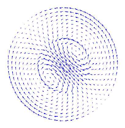
potential. The current distribution in Fig. 2(a) is
obtained for R1=0.5, R2=1, sigma1=10 and sigma2=1 when the optimal
currents are applied. Optimum currents are
obtained under norm(I)=1 constraint, and are I=[0.41 0.56 0.15 0.41
0.56 0.15]. Best currents are localized on the
object as can be seen from Fig.2 (a).
(a)
(b)
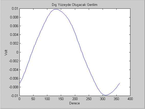
Fig. 2. (a) Current distribution in the object when optimum coil currents
are applied. (b) Potential calculated at the
boundary of the object.
V. CONCLUSION
In this work, a discrete coil induced current EIT system is analyzed.
The purpose of new configuration was to control the
current distribution inside the object without moving coils. It was
shown through examples that this has been successfully achieved. The currents
that maximize the distinguishability are obtained for two different constraints.
Further research will
focus on obtaining the optimum currents for eccentric inhomogeneities
and on determining minimum detectable object radius
for both cases.
REFERENCES
K. Boone, D. Barber, B. Brown, Review Imaging with Electricity: Report
of the European Concerted Action on
Impedance Tomography , Journal of Medical Engineering & Technology,
vol:21, pp:201-232, 1997.
I.L. Freeston, R.C. Tozer, Impedance Imaging Using Induced Currents,
Physiological Measurement, vol:16,
supp3A, pp:257-266, 1995.
Koksal and Eyuboglu, 1995, "Determination of optimum injected current patterns in electrical impedance tomography," Physiological Measurement, V.16, pp.A99-109. article.pdf
B.M. Eyuboglu, A. Koksal and M. Demirbilek, "Distinguishability analysis
of an induced current EIT system using discrete coils," Physics in
Medicine and Biology, Vol.45, No.7, pp.1997-2009, 2000. article.pdf